
Construction Documents: A Primer
Construction documents are the main deliverable produced by architects. They are drawings that show the contractor what to build and how to do it. Construction documents even have their own phase of an architecture project. This guide provides a basic introduction on how to read construction documents.
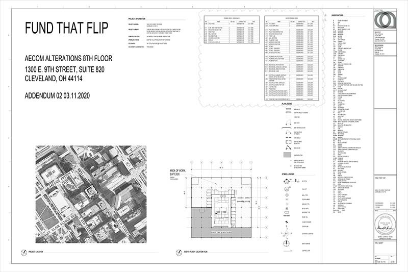
Fund That Flip Title sheet. Check out our blog series for more information about this project.
Title Block

Title block
Every sheet in a set of construction documents has a title block. The title block is a border on the sheet that contains project information and provides basic sheet organization.
Most title blocks incorporate a grid using numbers and letters along the sides that are used to reference where a drawing is on a sheet. Architecture drawings are big (24” x 36”) and sheets can contain many drawings.
All the information in a title block is along the right hand side because construction documents are bound along the left side and this allows one to flip through drawings easily. The project team is listed at the top of the sheet - this is where all the contact information for the various engineers and consultants on a project is listed. Further down on the sheet is the project information. This will include a name and address for the project as well as the revision information. Construction documents are often changed throughout the project and drawings are updated and issued multiple times. This is where the drawing version and date are indicated. Changes to the drawings are indicated with revision clouds which surround the changes and note the revision number when the change occurred. The bottom of the title block contains the sheet information. This is where one can find the sheet title and number.

Title Block Grid

Project Team Information

Project Information

Sheet Information
symbols
There are a lot of symbols used in construction documents that can be intimidating for those unfamiliar with them. There are different symbols for different disciplines but there (should) always be a symbol legend associated with a drawing. Our office usually puts a generic symbol on the title sheet and then more specific legends on the applicable drawings. A lot of information is contained in a single symbol. For example, the section symbol indicates the sheet the section drawing is on, “A101,” and the grid location of the section drawing on that sheet, “1”.
Typical architectural drawings

Floor Plan
The floor plan is the most ubiquitous and important drawing in a construction document set. This is a top down view of the space. Dimensions are given for all the built elements, wall/door/window types are indicated, and notes are called out on floor plans.

Reflected Ceiling Plan
Reflected ceiling plans - often abbreviated RCP - is just a floor plan that looks up instead of down. This is where all the ceiling elements - lights, ceiling types, HVAC diffusers - are shown.

Wall Sections
Wall sections are where the drawings begin to get more detailed. Plans are general drawings and are usually at a smaller scale to show the overall project. There’s only so much information that can be conveyed through plans. Wall sections show a cut through a wall to indicated how the wall should be constructed. Wall sections often include call out symbols which lead to an even more detailed drawing of a certain element.

Interior Elevations
Interior elevations are a great way for architects to indicate the design intent for a space. These drawings are straight on views that face different directions. Elevations show the project as a person in the space would see it.

Schedules
Schedules are hugely important to a set of construction documents. We place the schedule sheet at the end of the architectural drawings. They include more information about various design elements.
Some typical schedules:
Door schedule - This gives each door a number and includes information such as size, material, and hardware.
Finish schedule - This schedule gives each material used an abbreviation and lists information like a description, manufacturer, and model number.
Equipment schedule - This could include any specialized equipment a project may call for or items like refrigerators and televisions.